Car Amplifiers
JL Audio e6450 Review: Six-Channel Class AB Car Amplifier
Published October 8, 2026
A research-based review of the JL Audio e6450 six-channel car amplifier: verified specs, bridging, filters, wiring, gain setting and who should still consider one.
The JL Audio e6450 is a six-channel Class AB car amplifier built to run a whole system from one chassis: a front pair, a rear pair and a subwoofer, each with its own gain control and filter. This review is based on JL Audio's owner's manual, published third-party measurements and owner reports. It is not based on hands-on testing, and nothing here describes how the amplifier sounds.
Short version: The e6450 is rated at 45 W x 6 into 4 ohms or 75 W x 6 into 2 ohms, and its channel pairs can be bridged for 150 W x 3 into 4 ohms (all at 12.5 V, per JL). Its real strength is flexibility: separate input modes, three independent filters and a fixed bass boost let one amp run an active front, rear and subwoofer layout. Its limits are modest power by current standards, a 60 A fuse and 4 AWG wiring requirement, no digital processing, and an old design that is no longer confirmed as a current JL product. It suits a simple, compact system or a period-correct restoration. It is a poor fit if you want a high-power subwoofer or DSP tuning.
Key specifications (verified)
Every figure in this table comes from the specifications page of JL Audio's e6450 owner's manual (document code E6450MAN-CH-03-2003) unless the notes column says otherwise. The manual states that specifications may change without notice.
| Parameter | Specification | Notes |
|---|---|---|
| Channels and class | 6 channels, Class AB | JL's Absolute Symmetry dual N-channel MOSFET output stage |
| Power supply | Unregulated MOSFET switching type | Output varies with supply voltage |
| Rated power, stereo | 45 W RMS x 6 at 4 Ω; 75 W RMS x 6 at 2 Ω | Rated at 12.5 V |
| Rated power, bridged | 90 W RMS x 3 at 8 Ω; 150 W RMS x 3 at 4 Ω | Rated at 12.5 V |
| Minimum load | 2 Ω stereo per channel; 4 Ω bridged | Lower loads can trigger protection mode |
| THD at rated power | Under 0.08% at 4 Ω per channel | 20 Hz to 20 kHz |
| Signal-to-noise ratio | Over 104 dB | Referred to rated power, A-weighted |
| Frequency response | 10 Hz to 25 kHz (+0, -1 dB) | |
| Damping factor | Over 200 at 4 Ω; over 100 at 2 Ω | Per channel, at 50 Hz |
| Slew rate | ±22 V/µs | |
| Inputs | Three RCA pairs; 8-pin high-level input | Differential inputs; 200 mV to 8 V RMS range; high-level input covers channels 1 to 4 |
| Filters | 12 dB/octave Butterworth, one per channel pair | Low-pass, high-pass or off; marked 50 to 200 Hz, actual 53 to 225 Hz per the manual's chart |
| Bass boost | +6 dB at 48 Hz on channels 5 and 6 | 0 to 12 dB with the optional RBC-1 remote knob |
| Fuse and power wire | 60 A AGU or MaxiFuse; 4 AWG minimum | Fuse within 18 in (45 cm) of the battery |
| Dimensions (L x W x H) | 17.7 x 9.25 x 2.36 in (450 x 235 x 60 mm) | |
| Current status | Not confirmed | I could not find a current JL Audio product page or discontinuation notice |
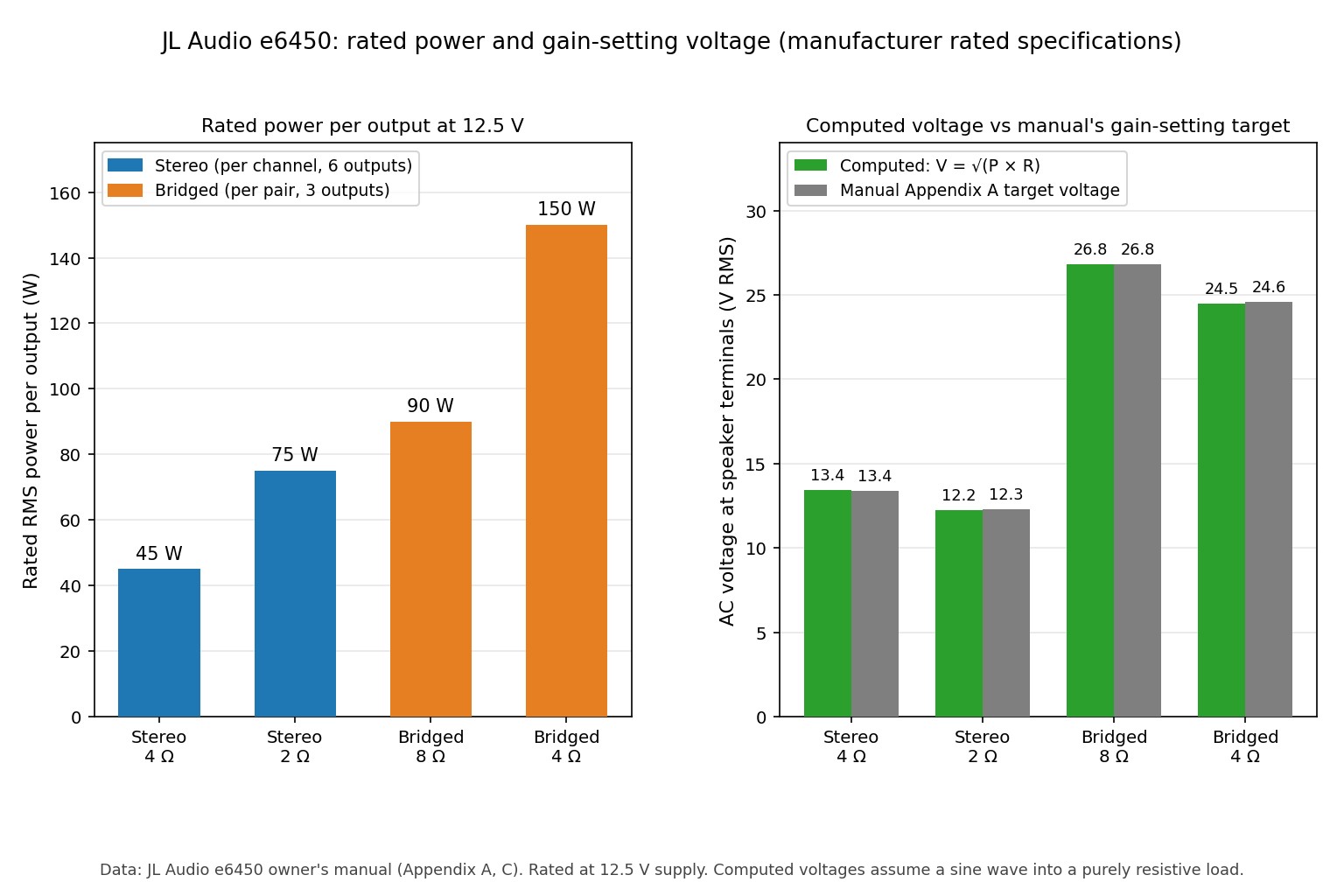
The right-hand chart is a consistency check. The voltage each rating implies is 13.4 V (4 Ω stereo), 12.2 V (2 Ω stereo), 26.8 V (8 Ω bridged) and 24.5 V (4 Ω bridged). The manual's gain-setting table lists 13.4, 12.3, 26.8 and 24.6 V, so the ratings and the setup procedure agree to within 0.1 V.
Design and features
Output stage and power supply
The e6450 pairs a Class AB output stage with an unregulated switching supply, so output power follows the vehicle's voltage. JL rates the amp at 12.5 V, and a running car with a healthy charging system is normally higher. Real output therefore depends on the car's electrical system as well as the amplifier.
Input options and the SUM mode
The amp has three RCA pairs and an 8-pin high-level connector for sources without line outputs, such as many factory radios. Channels 5 and 6 have no high-level inputs of their own. The Input Mode switch either takes their RCA inputs (Discrete) or sums the signals from channels 1 to 4 (SUM), so a factory radio with no subwoofer output can still feed a filtered subwoofer channel.
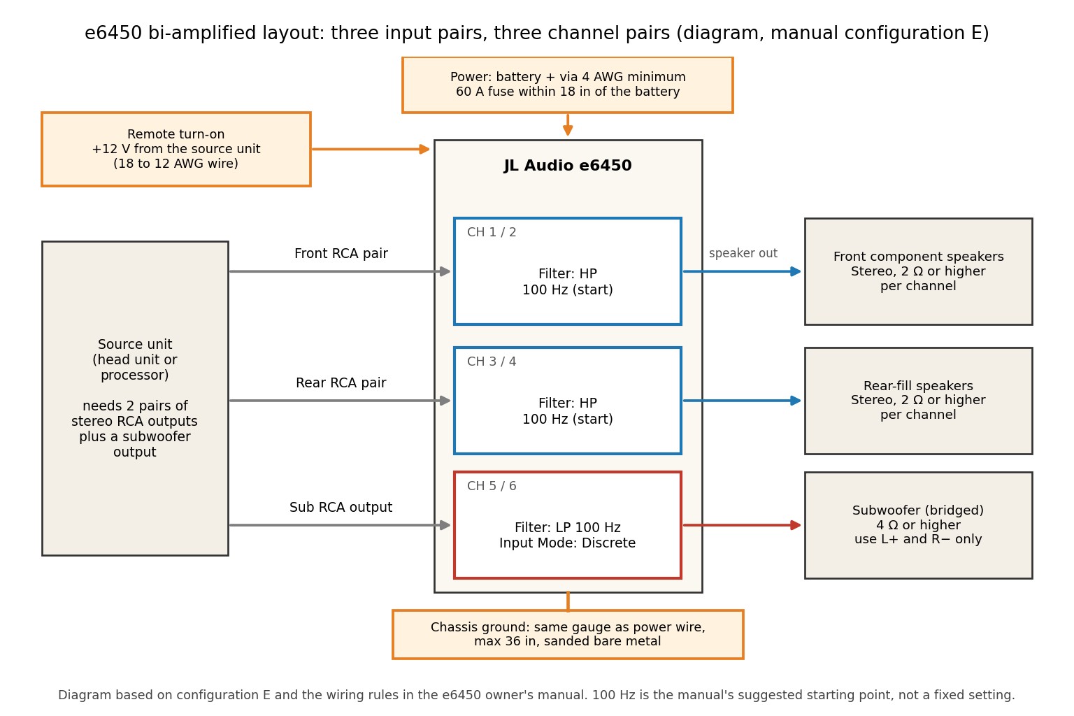
The manual describes five bi-amplified layouts (A to E) that differ mainly in how the inputs are connected and what the source unit can control. Layout E, drawn below, gives independent level control of all three pairs and needs two RCA output pairs plus a subwoofer output on the source.
Filters and bass boost
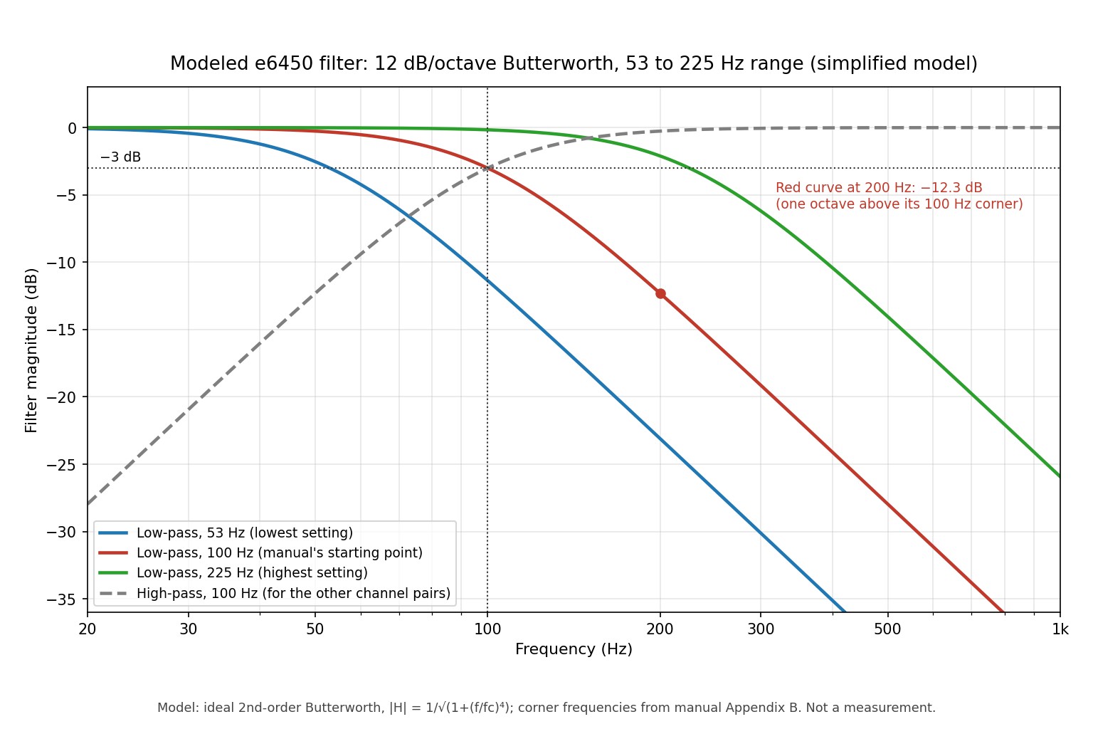
Each channel pair has its own 12 dB-per-octave Butterworth filter set to low-pass, high-pass or off. The dial is marked 50 to 200 Hz, but the manual's detent chart gives a real range of 53 to 225 Hz (the position marked 120 is 115 Hz, and the one marked 200 is 218 Hz). The manual suggests 100 Hz as a baseline for both low-pass and high-pass use.
The standard second-order Butterworth formula puts a 100 Hz low-pass 0.3 dB down at 50 Hz, 3.0 dB down at 100 Hz, 12.3 dB down at 200 Hz and 24.1 dB down at 400 Hz. A 12 dB per octave slope is gentler than the steeper slopes on many newer amplifiers and processors, so more signal above the corner frequency still reaches the subwoofer. This is a calculation for an ideal filter, not a measurement of a real unit.
The bass boost adds +6 dB at 48 Hz to channels 5 and 6, works only while that pair is set to low-pass, and sums the two inputs to mono. The optional RBC-1 remote knob makes it adjustable from 0 to 12 dB. One line of the printed manual says channels 3 and 4, but the rest of the page says 5 and 6, so that looks like a typo. Reset input sensitivity after enabling any boost, because boost raises subwoofer cone excursion.
Installation and setup notes
Safety: Disconnect the negative battery terminal before working on the wiring, and keep it disconnected until the fuse is installed. Protect any wire passing through the firewall with a proper grommet. Do not cut vehicle panels or drill without checking for wiring, fuel lines and structure behind them. Keep volume low during setup and protect your hearing.
Power, fuse and ground
JL specifies 4 AWG as the minimum power wire, with the main fuse within 18 in (45 cm) of the battery. For a single e6450 it recommends a 60 A AGU or MaxiFuse. The ground should be the same gauge, no longer than 36 in (90 cm), on sanded bare metal. Because many cars use thin 10 to 6 AWG battery ground and alternator cables, the manual advises upgrading them to 4 AWG once total fuse ratings exceed 60 A.
The 60 A figure matches the power rating. At 2 Ω all six channels are rated 75 W, or 450 W of output. At a published best-case efficiency of 60%, that needs about 750 W of input, or 60 A at 12.5 V. The 76 A maximum draw in the third-party data fits too: 6 x 107.8 W measured is 646.8 W, which at 60% efficiency and an assumed 14.4 V supply is about 75 A. I assumed 14.4 V because the quoted data does not state the test voltage.
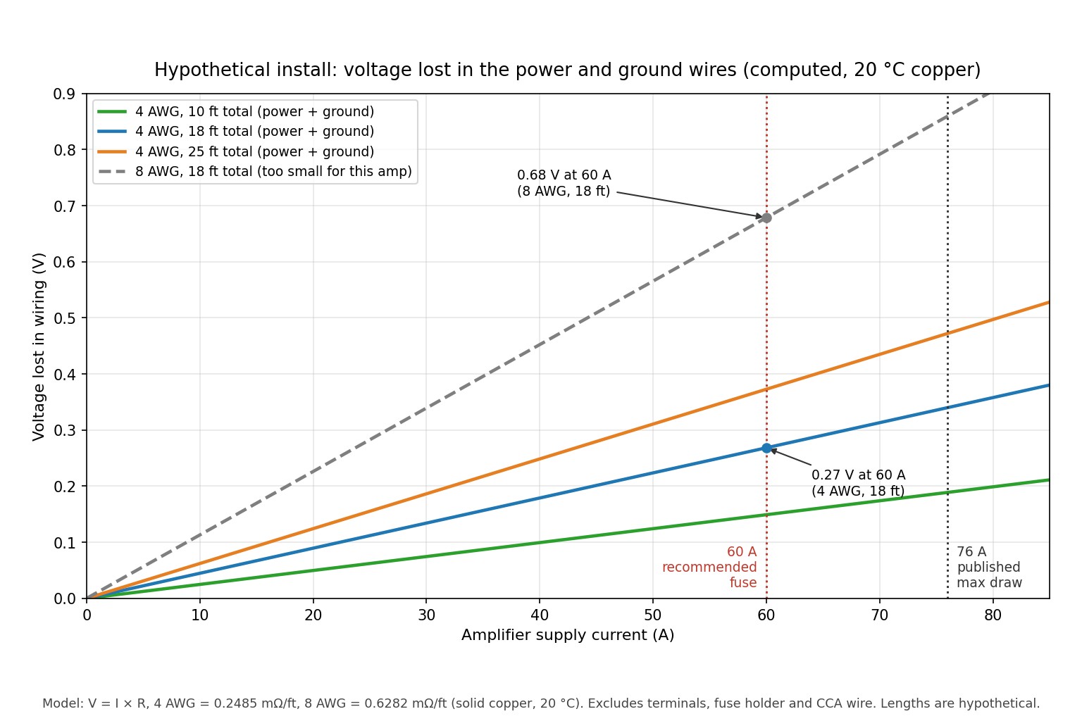
A hypothetical wiring example: 15 ft of 4 AWG power wire plus 3 ft of ground is 18 ft, or 4.47 milliohms at 0.2485 milliohms per foot (solid copper, 20 °C). At 60 A that drops 0.27 V and wastes about 16 W as heat. The same run in 8 AWG drops 0.68 V and wastes about 41 W. If output power follows the square of supply voltage (a simplification), a 14.4 V system loses about 0.16 dB with 4 AWG and about 0.42 dB with 8 AWG. The model ignores terminals, fuse holders and copper-clad aluminium wire, which all add resistance.
Setting input sensitivity
The manual's procedure needs a digital AC voltmeter and a 0 dB sine-wave test tone in the channel pair's range (50 Hz for subwoofer channels, 1 kHz for midrange). In outline:
- Disconnect the speakers from the amplifier outputs.
- Turn off all tone controls, loudness and EQ on the source and the amp, centre the fader and set any subwoofer level control to three quarters.
- Turn the Input Sens. control fully down and set the source volume to three quarters.
- Play the test tone and measure AC voltage at the speaker terminals (L+ and R- when bridged).
- Raise Input Sens. until the meter shows the target voltage from the table below, then reconnect the speakers.
| Nominal load | Stereo target (V) | Power at stereo target (W, computed) | Bridged target (V) | Power at bridged target (W, computed) |
|---|---|---|---|---|
| 8 Ω | 13.4 | 22.4 | 26.8 | 89.8 |
| 6 Ω | 13.4 | 29.9 | 25.6 | 109.2 |
| 4 Ω | 13.4 | 44.9 | 24.6 | 151.3 |
| 3 Ω | 12.8 | 54.6 | not recommended | - |
| 2 Ω | 12.3 | 75.6 | not recommended | - |
Target voltages come from the manual. The power columns are computed as V squared divided by the load and assume a resistive load, which a real speaker is not. The manual warns that raising any sensitivity control past its target causes audible distortion and can damage speakers.
What to check and how it should perform
The only measured data I found is a CEA-2006 test set attributed to CarSound.com, which I could read only as quoted in a forum thread. I could not retrieve the original page, so treat these as unverified third-party figures.
| Configuration | JL rating (12.5 V) | Measured, all channels driven | Difference | Measured, channels 5 and 6 only (50 Hz) | Difference |
|---|---|---|---|---|---|
| Stereo, 4 Ω | 45 W | 72.7 W | +2.1 dB | 107.6 W | +3.8 dB |
| Stereo, 2 Ω | 75 W | 107.8 W | +1.6 dB | 181.6 W | +3.8 dB |
| Bridged, 4 Ω | 150 W | 215.5 W | +1.6 dB | 363.3 W | +3.8 dB |
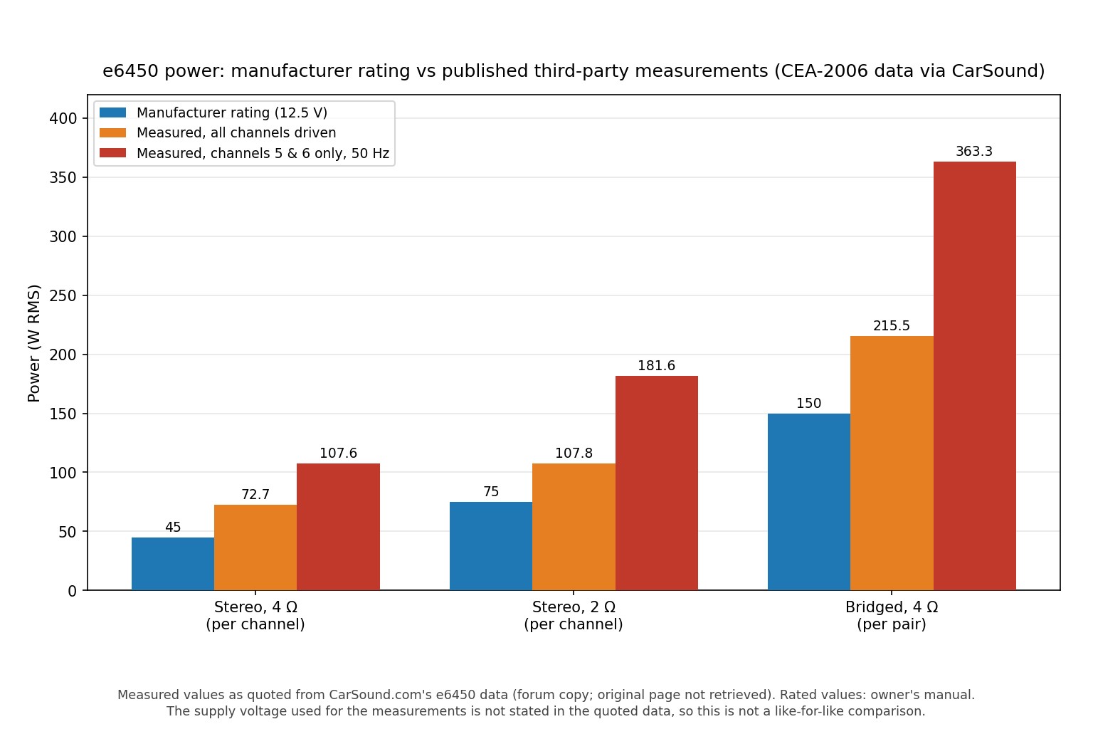
Two things stand out. Measured power exceeds the rating in every case, but voltage alone explains only part of it: if the test ran at 14.4 V, voltage scaling gives a factor of 1.33, while the measured ratios are 1.44 to 1.62 with all channels driven. The quoted data cannot say whether the rating is conservative or the test conditions were more favourable. Driving only channels 5 and 6 gives about 2.4 times the rating, which is typical of an unregulated supply that sags when all six channels draw current together, though only a bench test of a specific unit would confirm it.
The same data lists an idle draw of 1.9 A (roughly 24 W at 12.5 V) and a CEA-2006 signal-to-noise ratio of 100 dBA, which is not directly comparable with JL's over 104 dB referred to rated power. I did not verify heat behaviour in a real car, long-term reliability or sound quality.
Common mistakes to avoid
- Bridging with one input connected. The manual says both left and right inputs must be fed on a bridged pair, otherwise output drops, distortion rises and the amp can overheat.
- Wrong bridged terminals. Use only Left + and Right - when bridged. The other two terminals stay unused.
- Loads below the minimum. Under 2 Ω stereo or 4 Ω bridged, the amp may flash its red Protect light and cycle on and off.
- Setting gain by ear with bass boost on. The manual says to set sensitivity first and re-adjust if you later enable any boost.
- Forgetting the Input Mode switch. Discrete and SUM change what channels 5 and 6 receive.
- Thin or long ground wire. Keep the ground short, same gauge as the power wire and on bare metal, as shown in the wiring example above.
Pros
- One chassis can drive front, rear and subwoofer speakers with independent gain and filters per pair.
- Bridging needs no input inverter, and a bridged pair accepts a stereo signal directly.
- Both RCA and high-level inputs are supported, with SUM mode for sources that have no subwoofer output.
- The manual is detailed, with a documented gain-setting method and a filter frequency chart.
Cons
- Power is modest compared with many current subwoofer amplifiers; the whole amp is rated 450 W across six outputs.
- No digital signal processing and only a 12 dB per octave filter slope.
- The bass boost is a fixed +6 dB at 48 Hz unless you add the RBC-1 remote.
- It needs 4 AWG power and ground wire and a 60 A fuse, which raises installation cost.
- JL says there are no user-serviceable parts inside, so repairs go through a dealer. I could not verify current service availability.
- Current availability is unconfirmed, and used units are old enough that condition matters.
Who it is for and not for
A reasonable fit
The e6450 suits a compact, mostly full-range system where one amplifier replaces several: a front pair, a rear-fill pair and a single sealed or ported subwoofer, all fed from a head unit with RCA outputs. It also suits restorations of a period-correct system, and installers who want hands-on control of filters without a separate processor.
Not a good fit
It is a weak choice for a high-output bass system, because bridged power tops out at 150 W per pair by JL's rating. It also falls short if you want time alignment, parametric EQ or other DSP functions, or if you need a new product with a current warranty.
Alternatives
I did not verify specific competing models, so the table compares approaches rather than named products.
| Approach | Strengths | Trade-offs | Best when |
|---|---|---|---|
| Used e6450 (this amp) | One chassis, three filtered pairs, documented setup | Age, unverified service support, modest power | A simple active system on a small budget |
| Separate 4-channel amp plus mono sub amp | Subwoofer power can be chosen independently | Two chassis, two power runs and more space | You want more bass power than 150 W |
| Newer multi-channel amp with built-in DSP | Tuning tools beyond a basic filter | More setup complexity; check specifications of the exact model | You want EQ and time alignment |
| Powered subwoofer plus a 2- or 4-channel amp | Compact subwoofer solution | Less control over the sub amplifier's filters | Space is tight and bass needs are modest |
Buying advice
The listings I found were used, open-box or sold for parts, so I have no current new price. Forum posts from around 2006 describe the e6450 as a then-current model, so a used unit is likely many years old. Individual reports include a listing for a unit with only channel 1 working and an owner who had the internal board replaced after a wire failed. These are anecdotes, not failure rates. Listings also include marine versions named e6450M or M6450; I did not verify how their specifications differ.
- Test all six channels with known-good speakers and check that the green Power light comes on and the red Protect light stays off.
- Try each Filter Mode switch position and sweep the Filter Freq. and Input Sens. controls to listen for crackle or dead spots.
- Check the terminal blocks and set screws, and confirm the hex wrench is included.
- If you want adjustable bass boost, check whether the RBC-1 remote is included.
- Ask about any past repair, and confirm the return policy before you pay.
Final verdict
On paper, the JL Audio e6450 is a capable multi-channel amplifier for a small active system, with documented ratings, per-pair filters, bridging and a clear setup method. The published measurements suggest it delivers more than its ratings, but they are second-hand and from one source. Its limits are real: modest power, no DSP, and an old model with unconfirmed availability. If you can inspect a used unit and want an uncomplicated one-amp system, it deserves consideration; for serious bass output or tuning flexibility, look at newer options. No listening or bench testing was done for this review.
Sources and further reading
- JL Audio e6450 owner's manual, document code E6450MAN-CH-03-2003 (third-party hosted copy): specifications, gain-setting method and filter chart (page 7). Installation, bridging and bi-amplified layouts are on pages 3 to 6 of the same copy.
- CarSound.com measured performance data for the e6450, as quoted in a forum thread (original page not retrieved): forum copy of the CEA-2006 figures.
- Used and parts listings and owner threads, used only for anecdotal context on condition, marine versions and repairs.
Last reviewed: October 2026
JL Audio e6450 questions answered
How much power does the JL Audio e6450 make?
JL rates it at 45 W RMS x 6 into 4 ohms or 75 W RMS x 6 into 2 ohms, both at 12.5 V. Each pair of channels can be bridged for 150 W into 4 ohms or 90 W into 8 ohms. Because the power supply is unregulated, real output changes with the vehicle's voltage.
Can the e6450 run a subwoofer as well as speakers?
Yes. Channels 5 and 6 are intended for a subwoofer, either as a stereo pair down to 2 ohms per channel or bridged into 4 ohms or higher. The pair has its own low-pass filter, and an optional bass boost works only while that filter is on.
What fuse and wire size does the e6450 need?
JL specifies 4 AWG as the minimum power and ground wire, with a 60 A fuse within 18 inches of the battery for a single amp. The ground run should be no longer than 36 inches and attached to sanded bare metal. Larger gauge is advised if other amplifiers share the same power wire.
Does the e6450 have a built-in crossover?
It has one 12 dB-per-octave filter for each channel pair, selectable as low-pass, high-pass or off. The dial is marked 50 to 200 Hz, and the manual's detent chart shows an actual range of roughly 53 to 225 Hz. It is a simple filter, not a full processor.
What is the lowest speaker impedance it can drive?
The manual allows 2 ohms per channel in stereo and 4 ohms when a pair is bridged. Going lower can trigger the protection circuit, shown by a flashing red Protect light, and the output may cycle on and off. A steady red light instead indicates overheating.
Can I connect it to a factory radio with no RCA outputs?
Yes, the 8-pin high-level input accepts speaker-level signals for channels 1 to 4. Channels 5 and 6 have no separate high-level inputs, but the Input Mode switch can sum the other channels so a subwoofer pair still receives a signal.
How do I set the gain on the e6450?
JL describes a method using a digital AC voltmeter and a 0 dB sine-wave test tone with the speakers disconnected. You raise Input Sens. until the meter reaches the target voltage for your load, for example 13.4 V for 4-ohm stereo channels. Re-adjust it if you later switch on any bass or EQ boost.
Is the JL Audio e6450 still being made?
I could not confirm its current status from JL Audio. The manual I reviewed carries a 2003 document code, and the units now on sale appear to be used, open-box or for parts. Check with an authorized dealer before assuming new stock or service support exists.