Speaker Design
Speaker Crossover Design: Slopes, Phase and a Worked Example
Published October 9, 2026
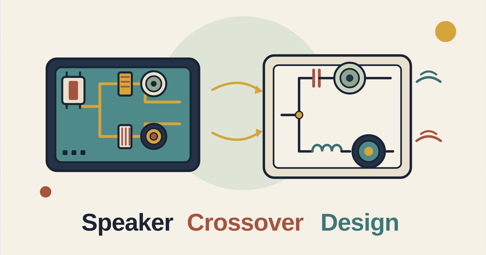
How speaker crossovers split the signal between drivers: filter order, Linkwitz-Riley and Butterworth alignments, driver impedance, and a worked 2.5 kHz example.
A crossover splits the signal so each driver only receives the frequencies it can reproduce well. Designing one comes down to four decisions: where to cross over, how steeply to roll off, which filter alignment to use, and how to deal with the fact that a real driver is not a resistor. This guide explains each decision with computed numbers, then works through a complete hypothetical 2.5 kHz two-way design.
Short version: For most two-way designs, a 4th-order Linkwitz-Riley (24 dB per octave) crossover sums flat and keeps both drivers in phase, but a 2nd-order Linkwitz-Riley with one driver wired in reverse is simpler and cheaper in a passive network. Pick the crossover frequency from the drivers' usable ranges, not from the filter. Always design the filter for the driver's real impedance, or flatten that impedance with a Zobel network first. An electrical model is a starting point, not a finished design: acoustic measurements decide the final values.
Safety: Test any new crossover at low volume. A wrong polarity, a shorted capacitor or an undersized tweeter filter can send full-range power to a tweeter and destroy it. In a vehicle, disconnect the battery negative before wiring, fuse power cables close to the battery, and check behind a panel before cutting or drilling.
Key terms
| Term | Meaning |
|---|---|
| Crossover frequency (fc) | The frequency where the low-pass and high-pass sections cross. For Butterworth filters each section is 3 dB down there; for Linkwitz-Riley filters each is 6 dB down. |
| Order | The number of reactive elements per filter section. Each order adds roughly 6 dB per octave of eventual roll-off. |
| Slope | How fast the response falls beyond fc, in dB per octave. 1st order is 6, 2nd is 12, 4th is 24. |
| Alignment | The filter family and its Q value: Butterworth (Q 0.707 for 2nd order) or Linkwitz-Riley (Q 0.5 for 2nd order). |
| Passive crossover | Inductors, capacitors and resistors between the amplifier and the driver. Handles full speaker power. |
| Active crossover | Filtering done before the power amplifier, in an analog crossover or a DSP, with one amplifier channel per driver. |
| Zobel network | A resistor and capacitor in series, placed across a driver to cancel the impedance rise caused by voice-coil inductance. |
| Re, Le | The driver's DC resistance and voice-coil inductance. They set how its impedance rises with frequency. |
How a crossover works
Why drivers need one
A woofer's cone is too heavy and large to reproduce the top octaves cleanly, and a tweeter's small diaphragm cannot move enough air at low frequencies without damage. Feeding each driver only its own band reduces distortion, protects the tweeter and lets the two drivers be tuned separately. The cost is that the filters add phase shift, and the two drivers overlap near fc, so how they sum there matters.
Filter order and slope
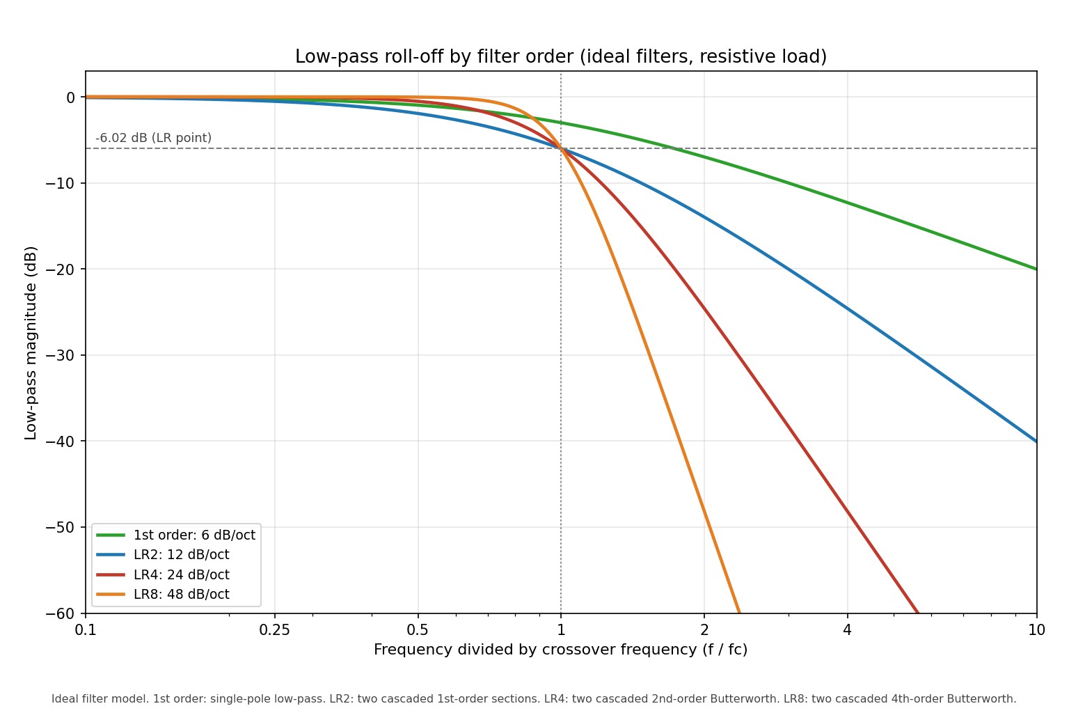
A steeper slope keeps more of the unwanted band out of each driver, which helps protect a tweeter and reduces the region where both drivers radiate. It also needs more parts in a passive network, and more phase shift. Figure 1 below shows the low-pass roll-off for four orders; the numbers are in the table that follows.
| Low-pass filter | 0.5 x fc | At fc | 2 x fc | 4 x fc |
|---|---|---|---|---|
| 1st order (6 dB/oct) | -0.97 dB | -3.01 dB | -6.99 dB | -12.30 dB |
| LR2 (12 dB/oct) | -1.94 dB | -6.02 dB | -13.98 dB | -24.61 dB |
| LR4 (24 dB/oct) | -0.53 dB | -6.02 dB | -24.61 dB | -48.20 dB |
| LR8 (48 dB/oct) | -0.03 dB | -6.02 dB | -48.20 dB | -96.33 dB |
These are electrical filter values. The acoustic slope you actually hear is the filter multiplied by the driver's own natural roll-off, so a woofer that already falls off above its range may behave like a steeper filter than the table suggests.
Butterworth versus Linkwitz-Riley
A Butterworth filter has the flattest possible passband, but each section is only 3 dB down at fc. Add the two outputs and, for a 2nd-order pair, you get a +3.01 dB bump at fc once one driver is reversed to avoid a null. A Linkwitz-Riley filter is built by cascading two identical Butterworth sections, which places each output 6.02 dB down at fc, so the pair sums to 0 dB. Figure 2 shows the computed sums.
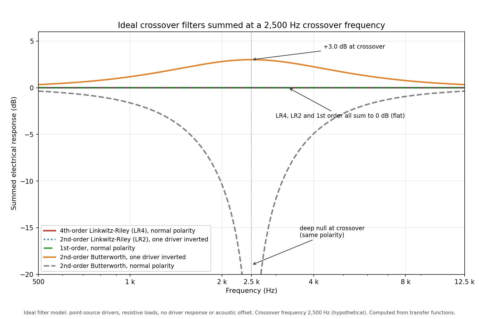
Phase is the other half of the story. A 2nd-order pair (Butterworth or Linkwitz-Riley) has outputs 180 degrees apart at all frequencies, so one driver must be wired in reverse polarity. A 4th-order Linkwitz-Riley pair is in phase at all frequencies and needs no inversion. A 1st-order pair is 90 degrees apart at all frequencies and sums flat in magnitude, but its slope is shallow. Rane's primer and Linkwitz's own papers cover the derivation.
Off-axis behaviour
Two drivers spaced apart radiate with a path difference that changes with vertical angle. With the drivers 0.14 m apart at 2,500 Hz (wavelength 0.137 m), the model predicts nulls at plus and minus 29.3 degrees for in-phase alignments (LR4, or LR2 with the tweeter reversed). The pattern is symmetrical about the axis. A 1st-order crossover with normal polarity has nulls near minus 47 and plus 14 degrees, so its main lobe is tilted. Figure 3 shows this.
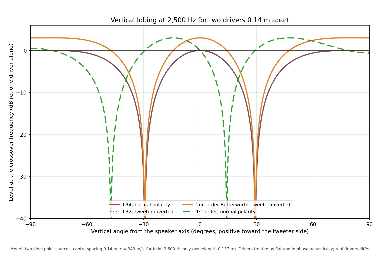
This is why the lobe width is a reason to keep driver spacing small relative to the wavelength at fc. A lower crossover frequency or closer driver spacing widens the useful lobe.
Passive filters and real driver impedance
Textbook component formulas assume a resistive load. A voice coil is a resistance (Re) in series with an inductance (Le), so its impedance climbs with frequency. A filter designed for a flat 6 ohm load will behave differently when it meets that rising impedance. The example below makes the size of the error concrete.
Worked example (hypothetical drivers)
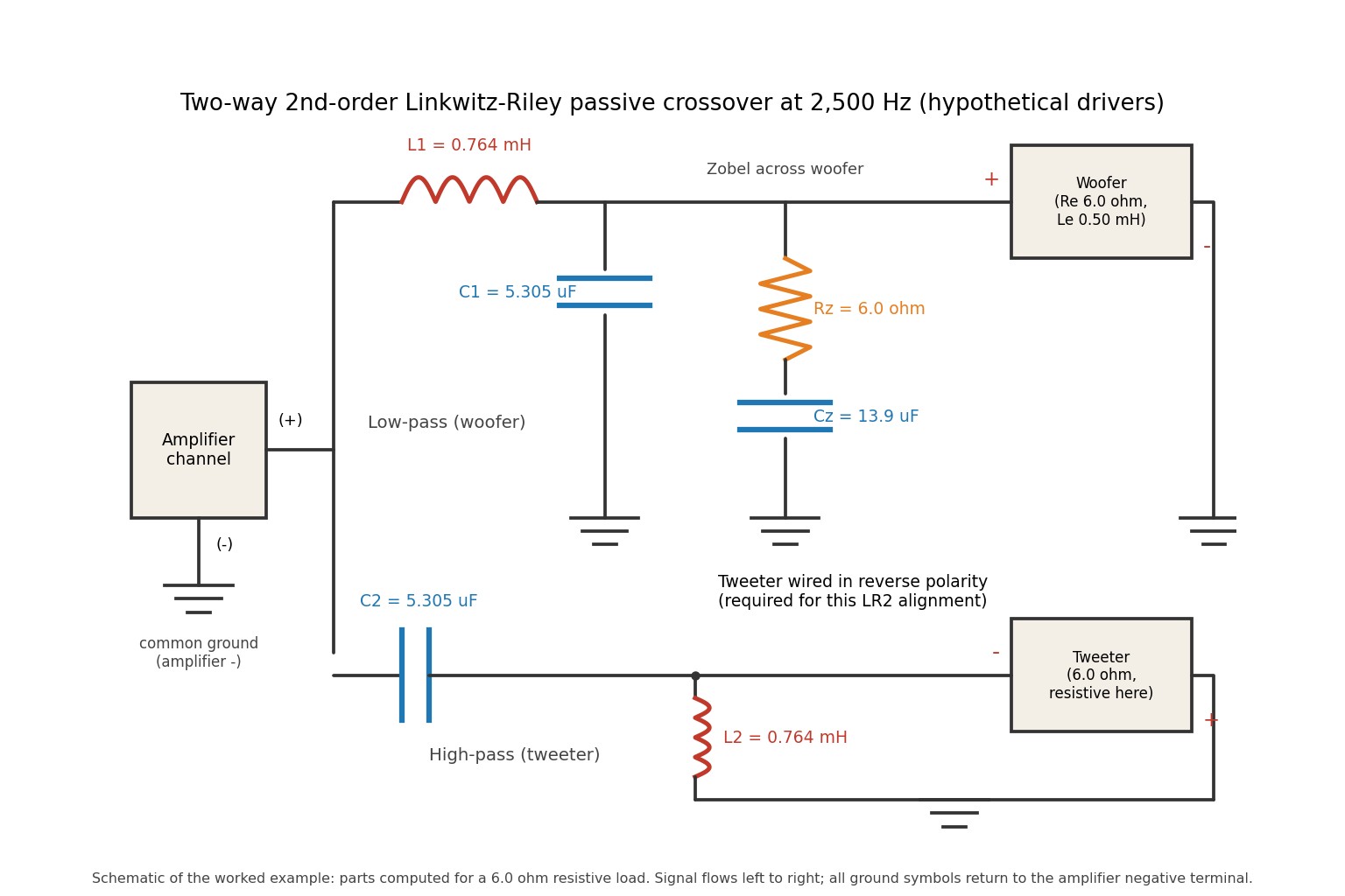
Take a hypothetical 6.5 inch woofer with Re 6.0 ohm and Le 0.50 mH, and a hypothetical tweeter treated as a 6.0 ohm resistor. Cross over at 2,500 Hz with a 2nd-order Linkwitz-Riley network. For a 2nd-order filter with quality factor Q into a load R, the series and shunt values are L = R / (Q x 2 pi fc) and C = Q / (2 pi fc x R). With Q = 0.5 and R = 6.0 ohm, the computed values are:
| Part | Role | Value |
|---|---|---|
| L1 | Woofer low-pass, series | 0.764 mH |
| C1 | Woofer low-pass, shunt | 5.305 uF |
| C2 | Tweeter high-pass, series | 5.305 uF |
| L2 | Tweeter high-pass, shunt | 0.764 mH |
| Rz | Zobel resistor (equal to Re) | 6.0 ohm |
| Cz | Zobel capacitor (Le / Re squared) | 13.9 uF |
The woofer's impedance without a Zobel rises from 6.03 ohm at 200 Hz to 9.88 ohm at 2,500 Hz, 16.81 ohm at 5,000 Hz and 63.12 ohm at 20,000 Hz. With the Zobel it stays at 6.00 ohm across the same range, because the Zobel is chosen to cancel the inductance exactly in this simplified model. The effect on the filter output voltage at the driver terminals is large:
| Frequency | Target (6.0 ohm resistor) | Woofer, no Zobel | Woofer with Zobel |
|---|---|---|---|
| 1,000 Hz | -1.29 dB | -2.46 dB | -1.29 dB |
| 2,500 Hz | -6.02 dB | -1.69 dB | -6.02 dB |
| 5,000 Hz | -13.98 dB | -4.82 dB | -13.98 dB |
| 10,000 Hz | -24.61 dB | -22.63 dB | -24.61 dB |
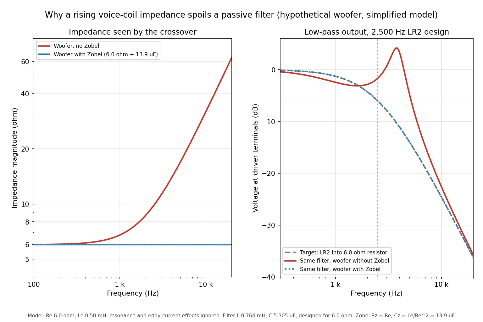
Without the Zobel the response peaks at about +4.17 dB near 3,770 Hz, and the -6 dB point moves from 2,500 Hz to roughly 5,170 Hz. In practice the crossover has stopped crossing over where intended.
What this model leaves out
- The woofer's mechanical resonance and the tweeter's resonance peak, which change impedance near their own frequencies.
- Eddy-current effects, which make real voice-coil impedance rise more slowly than a pure inductor. A published refinement uses a more elaborate compensation network; a simple Zobel is an approximation.
- Inductor winding resistance. A hypothetical 0.3 ohm in series with the 6 ohm woofer would cost about 0.42 dB of level.
- Baffle step, driver offsets and each driver's natural acoustic roll-off.
Choosing the crossover frequency
- Stay inside both drivers' usable ranges. The tweeter should cross well above its resonance frequency; installers commonly use a margin of roughly one and a half to two times resonance, which is a field rule of thumb, not a standard.
- Watch cone breakup. Cross the woofer over before its response turns ragged at the top of its range, as shown on the manufacturer's response curve.
- Consider spacing. The larger the driver spacing relative to the wavelength at fc, the narrower the clean forward lobe.
- Consider tweeter excursion and power. A lower fc and a gentler slope send more low-frequency energy to the tweeter.
Step-by-step design process
- Collect manufacturer response curves and impedance data for both drivers. Measure them if you can.
- Choose fc inside the overlap of the usable ranges.
- Choose an order and alignment. Use LR4 in an active system; use LR2 or a similar low-order filter in many passive systems to limit parts count.
- Decide whether to flatten each driver's impedance with a Zobel network.
- Compute the component values for the load the filter will actually see.
- Check polarity: reverse one driver for 2nd-order alignments.
- Build a prototype with clips or a breadboard before soldering. Use non-polarized capacitors and low-resistance inductors.
- Measure and adjust (see below).
| fc | L (mH), R = 6 ohm, LR2 | C (uF), R = 6 ohm, LR2 |
|---|---|---|
| 1,000 Hz | 1.910 | 13.26 |
| 1,500 Hz | 1.273 | 8.842 |
| 2,000 Hz | 0.955 | 6.631 |
| 2,500 Hz | 0.764 | 5.305 |
| 3,000 Hz | 0.637 | 4.421 |
| 3,500 Hz | 0.546 | 3.789 |
| 4,000 Hz | 0.477 | 3.316 |
For comparison at 2,500 Hz and 6 ohm, a 1st-order filter needs 0.382 mH and 10.61 uF, and a 2nd-order Butterworth filter needs 0.540 mH and 7.503 uF.
Measuring and checking
Measure each driver on its own, in its final enclosure or mounting, with the crossover in place. Check three things: the response of each section, the summed response with the tweeter at the correct polarity, and the summed response with it reversed. A deep notch at fc with the polarity you chose means the polarity is wrong. Always measure at the listening position or at a fixed distance and angle, and compare against the model rather than assuming the model is right. Test at low level first.
Comparison of alternatives
| Option | Slope | Sum at fc | Polarity | Parts per way | Main trade-off |
|---|---|---|---|---|---|
| 1st order | 6 dB/oct | Flat (0 dB) | Normal, 90 degrees apart | 1 | Shallow slope, tilted lobe, tweeter exposed to low frequencies |
| 2nd-order Butterworth | 12 dB/oct | +3.01 dB | Reverse one driver | 2 | Peak at fc |
| 2nd-order Linkwitz-Riley | 12 dB/oct | 0 dB | Reverse one driver | 2 | Gentle protection for the tweeter |
| 4th-order Linkwitz-Riley | 24 dB/oct | 0 dB | Normal, in phase | 4 | More parts and tolerance sensitivity in a passive network |
Strengths and limits of this approach
The electrical model gives exact filter values and makes polarity and summing easy to reason about. Its limits are real: it assumes drivers that radiate from the same point, with flat response, in phase, and with predictable impedance. Real drivers have none of those properties, so the model is a starting point and acoustic measurement does the final work.
Common mistakes
- Designing for the nominal impedance printed on the driver instead of its actual impedance at fc.
- Forgetting to reverse one driver in a 2nd-order crossover.
- Crossing a tweeter too close to its resonance.
- Using polarized electrolytic capacitors in a signal path.
- Assuming a flat electrical sum means a flat acoustic sum.
- Ignoring inductor resistance and capacitor tolerance.
- Testing at high volume first.
Sources and further reading
- Rane Note 160: Linkwitz-Riley Crossovers, A Primer
- Linkwitz Lab: Crossovers
- W. M. Leach, voice-coil impedance compensation networks (Georgia Tech)
- Wavecor: Zobel networks for impedance linearization
Last reviewed: October 2026
Speaker Crossover Design FAQ
What is the difference between a Butterworth and a Linkwitz-Riley crossover?
A Butterworth section is 3 dB down at the crossover frequency, so a 2nd-order pair sums to a +3 dB peak there. A Linkwitz-Riley section is 6 dB down, so the pair sums flat. Linkwitz-Riley filters are made by cascading two identical Butterworth sections.
Why do I have to reverse one driver in a 2nd-order crossover?
The low-pass and high-pass outputs of a 2nd-order filter are 180 degrees apart at every frequency. Reversing one driver brings them into phase so they add instead of cancelling at the crossover frequency. A 4th-order Linkwitz-Riley pair is already in phase and needs no reversal.
Do I need a Zobel network?
Not always, but it helps when you design a passive filter around a driver whose impedance rises with frequency. In the hypothetical example here, leaving it out moved the woofer's -6 dB point from 2,500 Hz to about 5,170 Hz. It is most useful on woofers with larger voice-coil inductance.
What slope should I choose, 12 dB or 24 dB per octave?
A 24 dB per octave slope protects the tweeter better and limits driver overlap, but costs more parts in a passive design. A 12 dB slope is simpler and often adequate if the crossover frequency is well above the tweeter's resonance. In an active or DSP system, 24 dB is easy to implement.
How do I choose the crossover frequency?
Pick a frequency inside the overlap of both drivers' usable ranges, well above the tweeter's resonance and below where the woofer's response becomes ragged. Installers commonly leave a margin of roughly one and a half to two times the tweeter's resonance, as a rule of thumb. Then check the result with measurements.
Can I use these formulas with real drivers directly?
Only as a starting point. The formulas assume a resistive load, flat drivers and a shared acoustic centre, none of which is true in practice. Measure the impedance and response of your drivers and adjust the values.
Is an active crossover better than a passive one?
An active crossover filters before the amplifier, so it avoids inductor loss and impedance interaction and allows high-order filters easily. It needs one amplifier channel per driver. A passive crossover is self-contained and simpler to install, but is limited by the parts and the driver's impedance.
Why is my crossover response not flat even though the filter sums flat?
The flat sum is an electrical result for ideal drivers. Real drivers have their own roll-off, resonances and acoustic offsets that shift phase and level around the crossover frequency. Acoustic measurement and adjustment are needed to correct for these.